Tuesday, December 16, 2008

Winter Brings Highest Gains


Because I installed the collectors at an inclination to maximize gain at winter sun angles, my daily gains are at their highest on these clear sunny December days. Temperatures (daytime) have been hovering in the low 20's, so there is plenty of capacity in my heating system to put the solar gain.


A second 30 tube bank would be great right now, but even with the high angle of my collectors lowering the summer gain and the shading of the trees, I may have excess summer capacity. I will begin measuring the daily BTU gains calculated by my Vitotronic controller and post the results.


It is 12 noon. I am running dishwashers and the washing machine. The collector is putting out 130 degrees, all going to my DHW tank. It is keeping the DHW tank hot enough to supply 125 degree water to the tap, and supressing the boiler from firing. When the DHW use is over, in about 40 minutes, the DHW tank will quickly heat up to max temp (140 degrees). Then heat will be diverted to the heating storage tank.


Friday, October 24, 2008

Sunday, October 19, 2008

Energy Savings Accumulating

The final system programming is complete. A "Heat Monitor" statement has been built for the Domestic Hot Water and Space Heating tanks. The heat energy is measured in Watts and is calculated from the temperature differential across the collector and the flow rate during the period that the pump (either one) runs.


The programmed parameters are: collector input flow temp, collector return flow temp, flow rate (set at 1 gpm - actual measured flow), and pump relay "on" time.


The wattage is a "totalized" acculation in watts. There are two seperate "statements" that totaled, represent the solar energy gathered, stored and delivered to the home.


Sunday, October 12, 2008

System Temps and Fine Tuning the System

DHW Temps: The heating of the domestic hot water (DHW) by the controller (vitosolic) is working great. I am heating the DHW to 50C. I have a tempering valve which mixes cold supply water with the hot tank water to keep the hot water from being at excessive temps. I also have a hot water circulating loop. This is a common system used to stop a long wait for hot water at a tap in large homes. The problem is that the water circulating is not tempered, but at the actual tank temp, so the water from the tap starts out at full temp (50C). Not only that, but the higher temp in the circulating loop (even though it is insulated), will result in higher heat loss. All that, plus the PEX tubing used in my house plumbing will not tolerate much higher temps, so that is why I am limiting the DHW tank to 50C.

Heat Collection: The default differential settings for circulating glycol through the collector and into the storage tanks are starting 5C (9F) and stopping 3C (5F). With these default settings, the pumps only cycle for a short time, on the average only a few minutes. The short cycle time comes from converging temperatures. As the cooler fluid from the tank being heated is pumped to the collector, the collector temp drops, and drops faster than the tank temp rises.

To lengthen the cycle time, I will raise the starting temp. I will not lower the stopping differential temp because doing so will likely result in inadequate differential for heat transfer to occur. I plan on starting with raising the starting differential to 7C. The collector temp comes up quickly when solar gain is good (from 10AM to 3PM), so time between cycles should not be much longer. I am betting that the increased length of time between cycles will be matched by an increase in the time length of the cycles.

Radiant Heat Delivery: Another important operating aspect of the system is delivery of heat to the radiant floor system header. The pump (P6 on the schematic), starts and stops on a temperature differential between the tank (S5), and the return line temp of the Low Loss Header (S6).

The tank must be at a high enough temp to match the temp that the boiler delivers to the header to provide radiant heat to the floors. This is tricky because the boiler control system modulates the header temp based on the outside temp, and a day/night settings where at night the header is ran at a lower temp than during the day.

The radiant heat storage tank temp can only be set at one temp, so I have set it's max temp at the top of the outside temp/boiler temp heating curve. So far, my collection capacity is not enough to hit the tank limit. What is available is the differential temp that the header return (P6) can be set at. I have been monitoring the header temp during operation, and it has become evident the the header temp drops when a zone calls for heat. After measuring the Low Loss Header (S8 in the schematic, not connected to the Vitosolic) and the return (S6), I have generally seen a 30 degrees F (about 16 degrees C) differential during operation. Based on this, I have set the S5/S6 differential to turn on the P6 pump to start a 16C, and turn off at 12C.

I will be monitoring the effectiveness of the new settings and posting the results in a week.

Sunday, October 5, 2008

Heat Rejection System Scheme Tested

If you look at the schematic diagram for the system, you will see a heat rejection loop. This was intended to be used if the collector had heated both tanks to their limits.

Instead of using an exchanger coil and a fan, as shown in the Viessmann control scheme, I always intended to turn on a few selected radiant heat zones by overriding their thermostats and driving the zone valves open. Doing this means that I will not have to "waste" the heat.

This has been accomplished by using a temperature probe (S3) to operate a programmable thermostat in the Vitosolic controller (thermostat 1). The thermostat turns on the S3 output, which drives the coil (120 volt) of an "interposing" relay. The contacts of this relay short out across the zone thermostat and open the zone valve. I was able to do this because I "home ran" all the thermostats as well as the wires to the zone valve manifolds.

I wired in the relay today and lowered the thermostat on and off temps below the tank temp and turned the interposing heat rejection relay on and off. The thermostat was overridden and zone valve for the test zone opened and closed.

In order to understand the scheme, you need another piece of information. There is a pump that delivers hot water to the boiler low loss header (P6) on the schematic. Like all the other differential controls in the system, temperature is measured at the source (S3 in the tank), and destination (S6 at the header). When the source is 5 degrees centigrade above the destination, there is adequate heat differential for transfer. Once the P6 pump turns on, the boiler will be suppressed from firing and delivering heat, saving propane.

In order to maximize the benefits of this system during this winter, I will program the relay to open zone valves when the tank is 10 degrees above the low loss header operating temp and deliver heat to the main living area zone. This will take some occasional adjustments depending on the outside air temp, as the Viessmann boiler controls raise the low loss header temperature as the outside air temp drops according to a programmed curve.

Right now it is looking like I will need another vacuum tube array to have enough collection capacity to heat the DHW and effectively heat the house. As we progress into winter, the sun angle will drop clearing the bottoms of the tree foliage that blocks the mid-day sun and also reach the highest efficiency angle respective to the collector inclination, so time will tell.

Saturday, September 27, 2008

Vitosolic Controller Info

The Vitosolic controller prioritization of where it directs heat is functioning a little differently than I anticipated. Each "cylinder" (storage tank) is given a priority and has a set "max temp". I thought that the controller would direct heat entirely to the highest priority tank until it reached the "max temp", then it would begin directing heat to the next priority tank.

Instead, it directs heat to whichever tank is 5 degrees below the collector (remembering the that collector is normally rising in temp while the tanks stay relatively static in temps during solar collection period). This actually works just fine, but it means that the higher priority tank may not reach full temp as fast. Still, under this type of control, there is definitely no opportunity wasted to collect and store solar energy.

Sunday, September 21, 2008

Tubes Installed, System Operating

Installed the vacuum tubes this morning. Today's is cloudy with sun breaks, so the system is cycling the pumps. Later the array should get full sun and both DHW and Heating tanks should be fully heated. The angle of the collector is optimized for a low angle winter sun, the time when the most collection capacity is needed.

Saturday, September 20, 2008

System Ready for Vacuum Tube Installation

System flushed with hot water and a little detergent, then drained and charged with Tyfocor HTL to 27psi. This is a special propylene glycol mixture specified by Viessmann. I started with 5 gallons, but had to add approximately 1 gallon of water. Full strength was good for down to -35C, which is -21F. I checked it with an automotive anti-freeze tester (used to check ethylene glycol), and it only showed good for 15 degrees. I will buy another 5 gallons of Tyfocor and repump the system displacing the mixture before the real cold weather comes. I should be able to do it with introducing very little air.

Both circulation pumps that flow glycol to the collector, one for the DHW, and one for radiant heating, were ran and speeds set for the proper flow rates. All sensors were connected to the Vitosolic 200 controller (except for the one that will open zones in case of high temp in the radiant storage tank). The controller functions were checked by using cold and hot water to simulate temperature differentials that started the pumps.

I wanted to make sure that the collector circulation pumps would run so that when I install the vacuum tubes in the collector, the system would transfer heat from the collector and not overheat.

One last point about charging the system with glycol to 27psi. The specification is 37psi. I am guessing that the pressure is necessary to suppress boiling when the collector is running hot. I circulated some glycol through the DHW tank coil and heated up the system. The pressure came up to 30 psi when I got the temp up to 80F. So, I believe the pressure may not only come up to spec, but go higher when the system is in operation.

Wednesday, September 17, 2008

Collector Support Frame and Header Installed


The support frame was constructed out of Unistrut 1 5/8 and 3/4 electrical conduit supports. The piping is connected, including a vent on the outlet. Other than insulation on the piping, and establishing circulation, the collector is ready for installation of the vacuum tubes.


Saturday, September 6, 2008

Boiler Room Components Addition Nearly Complete

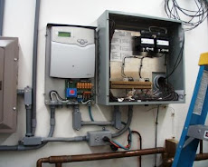
The solar capacity tank (which as my existing DHW tank) is now installed, filled and opened to the boiler system. It is shown on the left in the photo below. The new pump that will carry the heat from the collectors to the existing header that supplies my radiant heat system has also been ran. It is in the photos and is one of the two purple Grundfos pumps that are placed between the tanks.

The other two new pumps, one in the Solar Divicon and the other one below the 
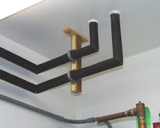
Divicon, are ready to be test ran once the tubing runs to the roof are done and the Vacuum Tube collector header and support frame for the tubes is installed. The tubes cannot be installed until the system is filled and circulation is established.

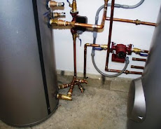
If you examine the picture closely, you will see a vertical line with a temp gauge and a flow meter in the line just to the right and above of the left hand tank.


These were installed to augment the temp gauge and flow meters in the Divicon, which monitor the flow and temp of the fluid on it's way to the collector from the DHW tank, and the temp of the fluid coming back from the collector. The added flow and temperature metering is to monitor the fluid from the solar capacity tank used for radiant heat going back to the collector, that ties in down stream of the Divicon, and would otherwise not be monitored. Each flow comes from a separate pump. Referring to the schematic would make this a little less confusing. Clicking on it should expand it to a readable size.


This is why I must be able to monitor both flows:
The correct flow rate for a single 30 tube collector is .8 gpm, and will be controlled by using one of the three speeds available on the pumps. The Vitosolic controller will only run one pump at a time, so a flow meter on each pump discharge is necessary to determine what speed setting will give the correct .8 gpm flow on each pump.

2nd reason for monitoring and maintaining equal and correct flows:
In addition to controlling the solar heating system, that neat little Vitosolic controller can also compute and generate a "heat statement" hopefully in the form of how many BTU's you have collected and distributed to your DHW and radiant heat. It does it by measuring temperatures (differential temperatures across the collector to be precise), and calculating the BTU's using a set flow rate programmed in. So, you must have equal and known flow rates for what goes across the collector for the calculated BTU's to be accurate.

Why do you need BTU's? Simple! This is all about saving money. In my case, I have to buy propane which has 91K BTU's per gallon. I am expecting to pay $2.50 to $3.50 a gallon this winter.

I've spent $12,500 on equipment (should get $2000 back with the Federal tax credit), so if propane averages $2.50 per gallon that is 4000 gallons that is required to be saved to pay back on my solar investment. Even with burning almost 2 cords of wood a winter, I still have to buy around 1400 gallons of propane a year. Even if my solar conversion only saves me from buying 1000 gallons a year (I still have to dry my clothes with propane), that is a 4 year payback! I would be thrilled if the payback is any less than 5 years! Time will tell.

Saturday, August 9, 2008

New Tank and System Tie-Ins Complete. What is Next.

The original DHW tank has been replaced and the new Vitocell double-coil tank is in now, plus the space heating header tie-ins, just upstream of the low-loss header are complete. The system is back up and running and working fine.

The next phase involves mounting the Solar Divicon, Pumps and Expansion tank on the wall. I have the old Vitocell DHW tank almost refitted for it's new job as the space heating capacity tank. After all the other aforementioned equipment is mounted (it all sets between the two tanks), I will move the tank into place and begin all the 3/4" piping for the system.

The 1/2" piping that will run from the Divicon to the Collectors (along with the the collector temp sensor wiring) will be left undone. The collectors are not mounted yet. I was going to custom weld up a frame to hold the collectors on the roof, but I am considering building the frame out of Unistrut. For you non-electricians, Unistrut is a kind of three-sided box tube that holds a variety of fixtures and clamps. Very versatile. It comes in a variety of materials: galvanized steel (cheapest), aluminum, stainless steel and fiberglass. The problem with galvanized is that the cut ends lose the zinc protection, and even cold-zinc'd and painted they eventually rust in the weather.

Friday, July 25, 2008

Project Moving Forward

Power system has been modified to make a space for the Vitosolic 200 controller, which has been configured for the solar system and mounted on the wall.

I will soon be bringing the heating/DHW sytem down briefly to cut into my existing system and install the tie-in points for the radiant heating system capacity tank (my existing Vitocell single-coil DHW tank). This will involve cutting into my 1 1/4 inch supply and return headers and installing two 1 1/4 by 3/4 tees, and installing a third tee in the return header for a temp well. Valves and short (16") copper tubing sections will be installed so that I can bring the system back up and still be able to solder and continue adding solar components.

Once this phase is complete, and the new DHW Vitocell double-coil tank has been prepped, I will bring the system back down to switch tanks and come back up with the new DHW tank. Completing this step will mean that the existing system will not have to be shut down any more, and the remainder of the entire solar system (collectors, Divicon, pumps, sensors and all), can be installed and the system tested. At this point, any "fine tuning" of the Vitosolic 200 controller programming can be done.

One note on the Vitosolic controller. It is a fine piece of technology, and has a great deal of optionality in it's programming. But, it is not for the novice. Even with 30 years of industrial controls experience working with programmable logic controllers and distributed computer control systems, it took several weeks of pouring over the manuals and asking lots of questions of not only the Viessmann tech guys, but the KW electronic guys for me to feel comfortable with the settings and options.

I'll post more as work on the system progresses, and hopefully be able to tout it's success an help to dispel the notion that solar hot water will not work in the coastal Northwest climate.